

Views: 0 Author: Site Editor Publish Time: 2026-09-30 Origin: Site


The increasing complexity of Industry 4.0 infrastructure requires high-speed data transmission, extreme miniaturization, and IP67+ environmental sealing for sensors, IoT devices, and machine control systems. This evolution has pushed industrial connector designs far beyond the capabilities of legacy manufacturing lines. Standard, off-the-shelf assembly machinery struggles to accommodate unique pin configurations, proprietary over-molding processes, and the stringent, zero-defect tolerances required for modern robotics and automation networks. Attempting to retrofit standard machines to handle complex hybrid connectors—which combine heavy-duty power transfer with fragile data communication lines—often results in high scrap rates, frequent downtime, and compromised electrical integrity.
To achieve scalable, high-yield production, manufacturers must evaluate Non-Standard Automation Solutions tailored to their specific connector architectures. This guide provides a technical framework for assessing, specifying, and implementing custom assembly and testing systems.
Customization is a Necessity, Not a Luxury: Complex industrial connector assembly requires non-standard customized equipment to handle proprietary form factors, delicate pin insertion, and specialized sealing requirements for harsh environments.
Integration of Assembly and QA: The most effective connector automation equipment seamlessly integrates mechanical assembly with in-line electrical and environmental testing to prevent downstream failures.
Flexibility Dictates ROI: Evaluating non-standard automation solutions requires prioritizing modularity and rapid changeover capabilities to accommodate multiple connector variants (e.g., power, signal, or hybrid) on a single line.
Risk Mitigation is Vendor-Dependent: Successful deployment relies on partnering with integrators who demonstrate proven expertise in micro-component handling, automated vision verification, and multi-disciplinary (electrical, mechanical, environmental) compliance.
Off-the-shelf automation platforms are engineered for uniformity and predictable form factors. When tasked with assembling modern industrial connectors, these legacy systems quickly reveal their mechanical limitations. One of the primary failure points is the inability to handle micro-pitch pin layouts. As connector footprints shrink to accommodate compact sensor housings, the distance between contact pins decreases to fractions of a millimeter. Standard pneumatic presses lack the fine force control required to insert these fragile pins. They operate on open-loop air pressure, meaning if a pin encounters resistance, the cylinder simply pushes harder, bending the contact or damaging the delicate gold plating.
Hybrid connectors present another significant hurdle. These components require the simultaneous assembly of heavy-duty power contacts and highly sensitive, high-speed data pins within the same polymer housing. Standard machinery struggles with this seamless component integration because the force profiles required to seat power pins will instantly crush data pins. Rigid tooling setups further compound the problem. Standard lines cannot adapt to the rapid product lifecycles and frequent design iterations inherent to modern industrial, sensor, and robotics connectors.
Legacy systems typically lack integrated, high-precision force monitoring during the mating and pressing stages. Without real-time data feedback, a standard machine will blindly push a misaligned component until it seats, creating micro-fractures in the housing or compromising the dielectric barrier. To overcome these physical limitations, manufacturers turn to non-standard customized equipment designed specifically for the unique geometry and material properties of the connector.
Open-loop pneumatic pressing causes high scrap rates due to uncontrolled insertion forces.
Inflexible vibratory bowl tracks fail to orient asymmetrical or highly fragile micro-components.
Lack of integrated vision systems allows dimensional defects to pass through to final assembly.
Rigid tooling nests prevent rapid changeovers between different connector SKUs.
Before engineering a custom solution, you must establish strict, quantifiable success criteria. Vague goals lead to poorly optimized machinery. The foundation of any successful custom assembly line rests on specific performance metrics that dictate the engineering of the machine.
Establishing baseline acceptable scrap rates is mandatory. For high-reliability industrial connectors, you should target a scrap rate of less than 0.1%. Custom automation must feature enough in-line verification to catch defects before they are permanently sealed or molded. The equipment must simultaneously satisfy stringent electrical, mechanical, and environmental standards in a single automated sequence. A connector is only viable if it passes dielectric testing, insertion force validation, and leak testing without requiring off-line secondary operations.
You must balance high-speed throughput with the necessary dwell times required for specific processes. Operations like ultrasonic welding, potting compound dispensing, or UV curing cannot be rushed without degrading the final product's structural integrity. Set aggressive but realistic targets for machine availability, performance, and quality right out of the gate. Custom machinery should be designed with predictive maintenance sensors to keep Overall Equipment Effectiveness (OEE) consistently high.
Performance Metric | Standard Off-the-Shelf Equipment | Custom Automation Solutions |
|---|---|---|
Typical Scrap Rate | 3% - 5% | < 0.1% |
Force Control Mechanism | Open-loop pneumatic cylinders | Closed-loop servo with load cells |
SKU Changeover Time | 4 - 8 hours (Manual retooling) | < 15 minutes (Recipe-driven PLC) |
Defect Detection | End-of-line manual QA sampling | 100% In-line vision and electrical testing |
Data Traceability | Batch-level tracking | Individual unit serialization and force-curve logging |
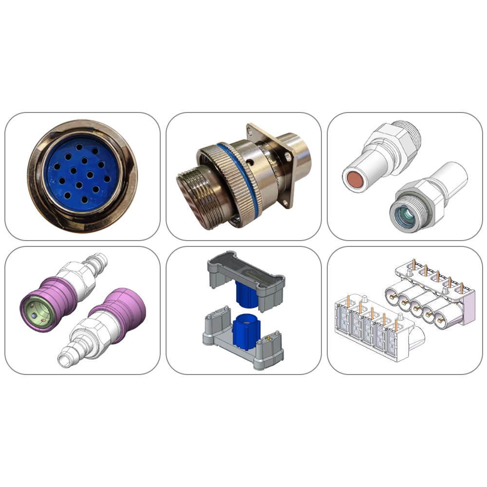
The heart of any connector assembly process is the pin insertion module. To achieve zero-defect insertion, custom systems utilize servo-driven actuators equipped with high-resolution encoders and piezoelectric load cells. This setup provides controlled force-distance monitoring during the entire insertion stroke. The PLC monitors the force curve in real-time. If the servo detects a sudden spike in resistance—indicating a misaligned pin, a burr in the plastic housing, or a bent contact—the system instantly halts the process. This closed-loop feedback prevents catastrophic damage to both the product and the machine tooling.
Feeding these fragile components into the insertion module requires highly specialized handling. Vibratory bowl feeding systems must be custom-tuned to the specific mass and geometry of the pins. For asymmetrical, highly fragile, or mixed-layout contacts, traditional bowl feeders may cause surface abrasion. In these cases, connector automation equipment utilizes advanced robotic pick-and-place mechanisms paired with flexible feeding platforms. These robots use vacuum end-effectors or micro-grippers to gently lift and orient the contacts without damaging the plating.
Industrial connectors deployed in harsh environments—such as outdoor IoT sensors, smart water meters, and factory floor robotics—rely heavily on robust environmental sealing. Achieving IP67 or IP68 ratings requires flawless execution during the over-molding and sealing phases. Custom automation utilizes precision dispensing systems for potting compounds and sealants. These dispensers feature volumetric controls, static mixers for two-part epoxies, and temperature regulation to maintain the exact viscosity of the compound, ensuring void-free encapsulation of the wire terminations.
O-ring placement is another notoriously difficult process to automate. Standard mechanical pushers often twist, pinch, or tear the elastomer seals during installation, leading to latent field failures. Custom solutions implement vision-guided robotic placement. The robot stretches the micro O-ring precisely enough to clear the connector threads or housing grooves, placing it gently into its designated seat. Post-placement vision cameras then verify that the O-ring is seated uniformly without any torsion or damage, guaranteeing environmental integrity.
Blind assembly is no longer viable in modern manufacturing. Implementing high-resolution machine vision is critical for verifying component geometry prior to final housing closure. Custom assembly lines deploy a combination of 2D and 3D machine vision cameras to inspect pin height, coplanarity, and true position. If a single pin in a 40-pin array is seated just a fraction of a millimeter too high, the entire connector will fail to mate properly in the field. 3D point cloud generation allows the system to measure the exact Z-axis height of every pin simultaneously.
Lighting techniques are just as important as the cameras themselves. Inspecting highly reflective metallic components against dark, light-absorbing polymer housings creates severe contrast challenges. Custom vision stations utilize specialized illumination—such as low-angle ring lights, coaxial lighting, or structured light patterns—to eliminate shadows and glare. This ensures the vision software can accurately detect edge profiles and surface defects on the micro-components, isolating bad parts before they proceed to the sealing or testing stations.
Building a connector mechanically is only half the battle; verifying its electrical integrity is what guarantees performance. The most efficient manufacturing lines integrate testing directly into the assembly sequence. Automating High Potential (Hi-Pot) testing is essential to verify dielectric withstand and insulation resistance, particularly for power transfer components. Custom testing modules apply high voltage across adjacent pins and the outer shell to detect any current leakage or arc-overs. By integrating this into a rotary dial or linear indexing chassis using specialized isolation relays, the system performs Hi-Pot testing without bottlenecking the overall line speed.
For data communication lines, signal integrity is paramount. Gigabit Ethernet forms the backbone of Industry 4.0 factory automation networks, requiring flawless data transmission. connector assembly and testing equipment automates continuity and low-level contact resistance testing. Precision pogo-pin blocks engage the connector terminals to measure resistance down to the milliohm level. Any deviation from the specified resistance indicates a poor internal crimp, a damaged pin, or compromised plating, allowing the PLC to immediately reject the unit.
Beyond electrical performance, industrial connectors must survive severe physical environments. In-line leak testing is deployed to verify the integrity of waterproof connector assemblies. Using air decay or mass flow testing methods, the automated station seals the connector and pressurizes its internal cavity. Highly sensitive transducers monitor for microscopic pressure drops over a few seconds, accounting for adiabatic temperature changes. If the pressure holds, the IP67/IP68 seal is validated. If it drops, the system flags the part for a torn O-ring or a void in the potting compound.
Automated mating cycle testing is also integrated to verify mechanical tolerances. The equipment physically engages a master receptacle with the newly assembled connector, measuring the exact insertion and withdrawal forces. This ensures the connector meets specified industry standards for robotics and machine control applications. If the insertion force is too high, it indicates dimensional distortion in the housing; if it is too low, the retention mechanisms may be faulty. Real-time force curves are logged for every single part, providing complete traceability.
When investing in custom machinery, rigid single-purpose designs severely limit future production capabilities. You must assess the system's ability to handle multiple SKUs on the same chassis. A well-designed line should allow you to switch between assembling M8, M12, and proprietary hybrid connectors with minimal downtime. This requires modular tooling nests mounted on kinematic bases that can be swapped out quickly using quick-release mechanisms without the need for specialized hand tools.
Changeover flexibility also relies heavily on software architecture. Recipe-driven PLC controls allow operators to select a new product variant from an HMI screen. The system then automatically adjusts servo stroke lengths, vision camera inspection parameters, and dispensing volumes to match the new SKU. When evaluating a vendor's proposed solution, closely examine the estimated time and tooling costs required for these line changeovers. A system designed around Single-Minute Exchange of Die (SMED) principles will drastically improve daily throughput.
Moving beyond the initial machine design requires a strict focus on long-term operational stability. Custom automation must be engineered for maintainability. Evaluate the Mean Time Between Failures (MTBF) and Mean Time To Repair (MTTR) for all critical stations. Systems should incorporate predictive maintenance technologies, such as vibration sensors on servo motors and flow meters on pneumatic lines, to alert maintenance teams before a catastrophic failure occurs.
Spare parts availability is another critical factor. Because custom machines utilize bespoke tooling, you must ensure the integrator provides a comprehensive spare parts package for all high-wear items upon delivery. Standardizing on universally available commercial off-the-shelf (COTS) components for PLCs, sensors, and pneumatics ensures your maintenance team can source replacements locally, minimizing unexpected downtime over a 5-to-10-year lifecycle.
The success of custom automation is entirely dependent on the engineering rigor of the integration partner. Never accept a concept at face value without physical proof. The importance of Proof of Principle (PoP) testing cannot be overstated. For high-risk assembly steps—such as inserting a uniquely shaped micro-pin or dispensing a highly viscous new potting compound—the vendor must build a small-scale test rig to validate the physics of the process before committing to the full system build. PoP testing eliminates assumptions and proves that the proposed mechanical action will actually work on your specific materials.
You must rigorously evaluate the vendor's Factory Acceptance Testing (FAT) and Site Acceptance Testing (SAT) protocols. The FAT takes place at the vendor's facility and must simulate full production conditions. The equipment must run continuously, processing thousands of parts to prove yield rates, cycle times, and the reliability of both power and high-speed data connector testing modules. The SAT repeats this validation on your factory floor, ensuring that shipping, reassembly, and integration with your facility's air and power supplies have not compromised the machine's precision.
A common pitfall in custom automation is the relentless pursuit of maximum speed at the expense of quality. Pushing custom machinery to its absolute mechanical limits often degrades precision. High-velocity pneumatic cylinders or aggressive servo movements can induce vibration, leading to bent pins, misaligned O-rings, or incomplete sealant dispensing. The faster the machine moves, the less time vision systems have to settle. If a camera snaps an image while the tooling nest is still vibrating, motion blur will cause false rejects.
To mitigate this risk, implement phased speed ramp-ups during the SAT phase. Start the machine at 60% of its maximum designed speed to establish a baseline of 100% yield. Gradually increase the speed in 5% increments, monitoring scrap rates at each stage. Utilize closed-loop feedback systems to automatically adjust speeds based on real-time quality metrics. If the vision system detects a slight increase in pin coplanarity variance, the PLC can dynamically slow down the insertion servo for the next cycle to restore precision.
Non-standard customized equipment inherently relies on bespoke machined parts, specialized robotics, and custom-ground tooling. These components are highly susceptible to supply chain delays. A delay in receiving a specialized 3D vision camera, a high-torque servo motor, or a specific brand of PLC controller can stall the entire integration project, pushing your product launch back by months.
Mitigate this risk by requiring vendors to identify critical path components during the very first design review. Secure long-lead items immediately after the conceptual design is approved, even before the final mechanical drawings are completed. By ordering specialized robotics and testing modules early in the initial design phase, you insulate the project timeline from unexpected global supply chain bottlenecks. Maintain transparent communication with the integrator regarding the delivery status of these critical components and be willing to approve alternative COTS brands if primary choices face severe delays.
Audit your current manual or semi-automated assembly stations to identify the specific mechanical bottlenecks causing high scrap rates.
Map out your exact SKU variability and define the physical dimensions for all connector variants planned for production over the next five years.
Compile a comprehensive User Requirement Specification (URS) detailing required cycle times, acceptable defect rates, and necessary in-line electrical and environmental tests.
Initiate Proof of Principle (PoP) testing with a qualified integration partner for any high-risk or proprietary assembly steps before committing to a full machine build.
Establish clear Factory Acceptance Testing (FAT) criteria based on continuous, high-volume production runs rather than short-burst demonstrations.
A: Non-standard customized equipment refers to bespoke machinery engineered specifically to automate unique manufacturing processes that off-the-shelf systems cannot accommodate. In connector manufacturing, this includes handling proprietary pin layouts, assembling hybrid power and data configurations, and executing specialized over-molding or sealing techniques tailored to a specific product geometry.
A: Industrial connectors often feature micro-pitch contacts, complex waterproof sealing, and strict high-speed data requirements for Industry 4.0 networks. Standard automation lacks the specialized tooling, high-resolution vision verification, and integrated force-monitoring necessary to assemble these delicate components without causing structural damage or high scrap rates.
A: Key features include servo-driven precision pressing with force-distance monitoring, vision-guided robotics for micro-component and O-ring placement, modular tooling nests for rapid SKU changeovers, and closed-loop feedback systems for real-time quality control and dynamic machine adjustments.
A: Effective integration relies on utilizing a unified PLC architecture where mechanical assembly stations immediately feed into automated testing modules. By placing Hi-Pot, continuity, and leak testing directly in-line, the system ensures defective units are identified and isolated immediately before further value or components are added.
A: Depending on the complexity of the assembly process, the number of integrated testing modules, and component availability, designing, building, and validating custom automation systems typically ranges from 6 to 12 months. This timeline spans from initial concept approval through to final Site Acceptance Testing (SAT).
A: Success is measured by analyzing the immediate reduction in manual labor dependencies and the drastic decrease in material scrap rates. Furthermore, custom automation increases hourly throughput and prevents costly downstream product failures in critical robotics or IoT applications, ensuring production efficiency and massive quality gains.


