

Views: 0 Author: Site Editor Publish Time: 2026-09-01 Origin: Site


Automotive connector manufacturing leaves zero room for error. A single micro-defect in a terminal block causes catastrophic system failures. Modern EV and ADAS architectures demand absolute reliability. Vehicle recalls damage brand reputation and compromise driver safety. You face a constant tension between scaling production volume and maintaining strict zero-defect tolerances. Manual assembly lines simply cannot keep up. Legacy semi-automated processes struggle when handling complex, miniaturized, or high-current components.
You need a structured, engineering-led framework for evaluating and procuring an Automatic Assembly Machine. This equipment must align perfectly with your specific production volumes, quality standards, and facility integration requirements. The right system transforms unpredictable manual labor into a highly controlled, data-rich manufacturing environment. We will break down the core evaluation dimensions, specialized automotive requirements, and implementation strategies necessary to select the optimal equipment for your facility.
Precision is Non-Negotiable: High-speed connector assembly requires integrated vision systems and electronic servo axes to ensure micron-level accuracy and immediate defect rejection.
Application Dictates Architecture: The choice of robotics (e.g., SCARA vs. Cartesian) and tooling depends heavily on whether the line processes standard wire-end connectors, miniaturized micro-connectors, or high-current EV terminals.
Traceability is Mandatory: Automotive compliance (IATF 16949) necessitates connector automation equipment with robust data logging and real-time process monitoring.
Transitioning from manual or semi-automatic equipment to a fully automated line requires clear volume thresholds. Low-volume runs might tolerate manual insertion. High-volume automotive contracts demand continuous throughput. You must define the exact point where automation becomes necessary to meet delivery schedules. This threshold usually aligns with the award of a multi-year OEM platform contract. You cannot justify the capital expenditure for a fully automated cell on a short-run aftermarket part.
Calculating required units per hour (UPH) involves more than just dividing daily demand by shift hours. You must factor in acceptable overall equipment effectiveness (OEE). Planned downtime for maintenance, material replenishment, and shift changes eats into available production time. A machine rated for 1,200 UPH might only deliver 950 UPH in real-world conditions. Build a 15% to 20% buffer into your cycle time targets. This buffer absorbs minor micro-stoppages and ensures you meet strict automotive delivery windows without requiring emergency weekend shifts.
OEE calculation breaks down into three distinct metrics: Availability, Performance, and Quality. Availability accounts for planned and unplanned stops. Performance measures the actual running speed against the theoretical maximum speed. Quality tracks the ratio of good parts to total parts produced. If your takt time dictates a finished part every 2.5 seconds, your machine cycle time must be engineered for 2.0 seconds to account for the 80% OEE reality on the manufacturing floor.
Production Tier | Annual Volume | Recommended Assembly Method | Primary Constraint |
|---|---|---|---|
Low Volume / Prototype | < 250,000 units | Manual assembly with fixture assists | High labor cost per unit |
Medium Volume | 250,000 - 1,000,000 units | Semi-automated rotary dials | Operator loading speed limits throughput |
High Volume / OEM Platform | > 1,000,000 units | Fully automated multi-station cells | Requires strict component dimensional stability |
Automotive manufacturers no longer accept reactive quality control. Sorting good parts from bad parts at the end of the line is a failed strategy. You must move to in-line, predictive quality assurance. Every insertion, crimp, and lock must be verified the millisecond it happens. If a pin bends during insertion, the machine must isolate that specific assembly immediately. It cannot allow the defective sub-assembly to proceed to the next station.
Scrap rates carry massive implications for high-value automotive components. EV connectors utilize heavy copper alloys and complex shielding materials. Scrapping a fully assembled high-voltage connector due to a missing seal at the final station destroys your profit margin. An effective automotive connector assembly machine catches errors at the component level. It rejects a single bad terminal before it gets locked into an expensive multi-way housing. This proactive rejection strategy protects your yield rates and ensures compliance with zero-defect mandates.
Specific defect types require targeted mechanical solutions. Pushed-back pins occur when the terminal fails to lock into the housing lance. The automation must perform a physical push-back test or utilize high-resolution vision to verify the terminal position assurance (TPA) component seats fully. Rolled seals happen when the insertion tooling pinches the elastomer during assembly. The machine must use specialized expansion jaws to open the seal slightly before sliding it over the wire insulation.
Selecting the right kinematic structure dictates the success of your assembly line. SCARA (Selective Compliance Assembly Robot Arm) robots dominate high-speed connector assembly. They offer extreme rigidity in the Z-axis. This rigidity is perfect for the vertical insertion forces required to seat terminal pins into plastic housings. Cartesian systems work well for heavy payload transfers but lack the rapid point-to-point speed of a SCARA arm.
Modern connector assembly often involves up to 20 sequential working steps. These steps include pin insertion, secondary locking, seal placement, and continuity testing. Electronic servo axes and precise curve control manage these steps. Servo control allows the tooling to approach the housing rapidly, decelerate just before contact, and apply controlled force during insertion. This prevents damage to fragile micro-pins. Pneumatic cylinders lack this programmable deceleration, often slamming components together and causing micro-fractures in the plastic housings.
Multi-robot orchestration presents a significant engineering challenge. A high-throughput cell might synchronize 10 or more SCARA robots working over a single indexing dial or linear conveyor. The master PLC must manage collision zones dynamically. It ensures high speed with optimum accuracy while eliminating any risk of robotic interference. This requires advanced motion control algorithms and deterministic communication networks. The robots must share a common coordinate system, allowing them to hand off parts seamlessly without stopping the primary indexing motion.
Actuation Method | Force Control | Speed Profile | Best Application |
|---|---|---|---|
Pneumatic Cylinder | Low (Regulator based) | Bang-bang (End stops) | Simple clamping, part ejection |
Stepper Motor | Medium (Open loop) | Programmable | Low-force positioning, indexing |
Servo Press | High (Closed loop feedback) | Fully programmable curves | Terminal insertion, TPA seating |
Vision systems serve as the eyes of your automation. 2D and 3D machine vision cameras verify pin depth, terminal alignment, and seal integrity. A 3D profiling laser can scan a fully loaded connector block in milliseconds. It confirms that every single pin sits at the exact required height. If a pin is pushed back even 0.2 millimeters, the vision system flags the part for rejection. Lighting plays a massive role here. You must use multi-spectral or structured lighting to eliminate shadows inside deep connector cavities.
Visual inspection alone is insufficient. You must implement force-distance monitoring during the physical insertion process. Piezoelectric load cells measure the exact force applied as the pin enters the housing. The system plots this force against the distance traveled. A bent pin causes an early force spike. A malformed housing cavity results in a lower-than-expected insertion force. The machine detects these anomalies instantly and aborts the cycle before causing further damage.
Beyond vision and force, you must integrate electrical and pneumatic testing. LVDT (Linear Variable Differential Transformer) probes physically touch the pins to verify continuity and seating depth simultaneously. For sealed automotive connectors, the machine must perform in-line leak testing. A pressure decay test injects air into the mated connector and monitors for pressure drops, ensuring the radial seals will withstand engine compartment environments.
Automotive life cycles dictate that your equipment will eventually need to run different part numbers. The machine must handle multiple connector variants using family tooling. Modular gripping heads and programmable servo positions allow the equipment to adapt to different housing lengths or pin counts without requiring entirely new mechanical stations.
Utilizing a standardized machine chassis provides massive advantages over a fully custom build. A standardized base platform reduces engineering lead times. It lowers fabrication risks and improves baseline reliability. The core frame, safety enclosures, and primary indexing mechanisms are already proven. Engineers only need to customize the specific tooling nests and end-of-arm effectors. This approach cuts months off the delivery schedule and ensures the foundational mechanics are battle-tested.
Quick-change tooling minimizes downtime during product changeovers. Operators should not need hand tools to swap out insertion blades or holding fixtures. Implement kinematic mounts and quick-disconnect pneumatic fittings. Pair this mechanical flexibility with recipe-driven software interfaces. The operator selects the new part number on the HMI, and the machine automatically adjusts servo stroke limits, vision inspection parameters, and force monitoring thresholds. Applying SMED (Single-Minute Exchange of Die) principles to connector assembly keeps your OEE high even with frequent batch changes.
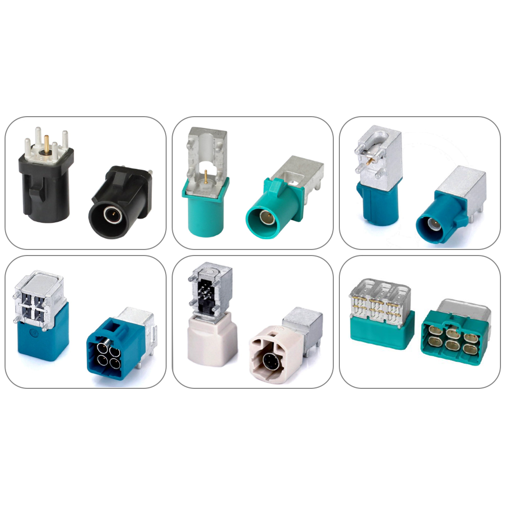
Electric vehicles completely alter the connector landscape. Assembling high-voltage and high-current connectors introduces unique mechanical challenges. You are dealing with heavier gauge wires, thicker copper terminals, and specialized electromagnetic shielding components. The physical mass of these parts requires robust automation equipment. You cannot use standard micro-connector tooling to handle a 50mm² battery cable.
Higher insertion forces are mandatory. Pushing a massive 8mm busbar terminal into a rigid polymer housing requires heavy-duty servo presses. Standard pneumatic cylinders lack the necessary control and force capacity. Specialized crimp-force monitoring becomes critical. A poorly crimped high-voltage cable creates excessive electrical resistance. This resistance generates heat, potentially leading to thermal runaway in the vehicle. The assembly machine must monitor the crimp signature of every single heavy-gauge connection.
High-voltage connectors also require High-Voltage Interlock Loop (HVIL) assembly. The machine must insert and verify these secondary low-voltage pins that confirm the main high-voltage connection is secure. Additionally, the automation must handle the assembly of braided metal shielding. This often involves ultrasonic welding stations integrated directly into the assembly cell to bond the shield to the connector shell, requiring specialized acoustic enclosures and fume extraction.
Conversely, ADAS (Advanced Driver Assistance Systems) and infotainment networks drive extreme miniaturization. Micro-connectors feature pins as thin as a human hair. Handling these components requires incredible finesse. A slight misalignment during feeding will crush the terminal. The tooling must be machined to exacting tolerances, often utilizing wire EDM (Electrical Discharge Machining) to create insertion blades that fit between 0.5mm pitch pins.
Advanced feeding mechanisms replace traditional vibratory bowls for these delicate parts. Vibratory bowls can scratch plating or bend micro-pins as the parts tumble against each other. Vision-guided flexible feeders present a superior solution. A multi-axis vibration plate spreads the fragile components gently. An overhead camera locates properly oriented parts, and a high-precision robot picks them up individually. This eliminates abrasive tumbling and prevents damage to highly fragile miniaturized housings.
Static electricity poses a massive threat during small part assembly. Lightweight plastic housings will stick to the tooling or repel each other due to static charge. The automation cell must incorporate active static elimination. Ionizing air blowers flood the handling zones with positive and negative ions, neutralizing the static charge and allowing the micro-components to drop cleanly into their nests. Vacuum grippers often replace mechanical parallel grippers to handle these tiny housings without applying crushing force.
wire-end connector assembly introduces the complexity of flexible materials. Rigid plastic housings behave predictably. Copper wire and silicone insulation do not. Cables retain memory from being spooled. They droop, twist, and resist precise positioning. The automation must account for this variability. You cannot push a flexible wire; you must pull it or guide it through tightly toleranced tubes.
A fully integrated cell manages wire stripping, terminal crimping, and housing insertion sequentially. Specialized wire grippers hold the cable firmly without crushing the insulation. The stripping module must remove the jacket cleanly without nicking the underlying copper strands. Once crimped, a servo-driven insertion head guides the terminal into the housing. The system must verify the primary lock engages, often by performing a slight pull-back test on the wire itself.
Seal loading adds another layer of complexity to wire-end assembly. Hard shell connectors require ribbed silicone seals to prevent moisture ingress. The machine must orient the seal, expand it slightly, and slide it over the stripped wire before the terminal is crimped. The vision system must then verify the seal is not rolled or torn. Crimp Force Monitoring (CFM) analyzes the force curve during the crimping stroke to detect missing copper strands or insulation caught inside the wire barrel.
The automotive industry enforces strict traceability standards. IATF 16949 compliance requires you to track the manufacturing history of every single safety-critical connector. Component-level traceability is no longer optional. The assembly machine must integrate laser marking or barcode reading stations. A 2D DataMatrix code is etched onto the plastic housing, serving as the unique identifier for that specific assembly.
Secure data logging forms the backbone of this traceability. The machine's PLC and SCADA systems must handshake seamlessly. Every time a connector is assembled, the system logs the insertion force curve, the vision inspection image, and the leak test results against that specific serial number. This data is pushed to the plant's Manufacturing Execution System (MES). If an OEM requests an audit due to a field failure, you can retrieve the exact manufacturing parameters for that specific connector instantly.
Network reliability is critical for data retention. The machine must feature local SQL database buffering. If the plant network goes down, the machine continues to run, storing the traceability data locally on an industrial PC. Once the network connection restores, the system automatically pushes the buffered data to the central server. Automotive contracts often require this data to be retained for up to 15 years, demanding robust data architecture from the machine builder.
New connector automation equipment rarely operates in isolation. It must interface with upstream injection molding machines or downstream end-of-line testing stations. Bottlenecks frequently occur at these handover points. If the upstream molding machine cycles slower than the assembly dial, the automation starves for parts. If downstream testing takes too long, the assembly machine blocks and stops production.
Map out communication protocols early in the procurement phase. Ensure seamless compatibility between the new machine and existing facility infrastructure. Standardize on robust industrial networks like PROFINET or EtherCAT. Define the exact handshake signals required for part transfer. Establish clear accumulation buffers between machines to absorb minor cycle time variations and prevent cascading line stoppages.
Material replenishment strategies must be defined upfront. High-speed machines consume reels of terminals and bins of housings rapidly. You must integrate Autonomous Mobile Robots (AMRs) or automated guided vehicles to deliver raw materials to the cell. The machine should feature dual-reel unwinding stations, allowing the operator to splice a new reel of terminals without stopping the primary assembly process.
Complex automation introduces the risk of operational errors. A highly capable machine becomes a liability if the floor staff cannot run it effectively. Overly complex HMIs (Human-Machine Interfaces) frustrate operators and lead to incorrect parameter entries. A wrong offset entered during a tool change can crash a servo axis and destroy expensive tooling.
Specify the need for intuitive controls. The HMI should utilize clear, graphical representations of the machine. Error diagnostics must be explicit. Instead of displaying a cryptic hexadecimal fault code, the screen should show a 3D image of the exact sensor that failed, along with troubleshooting steps. Demand comprehensive vendor-supplied training programs. This training must cover routine operation, preventative maintenance, and basic fault recovery to ensure a smooth hand-off to your facility floor.
Implement Role-Based Access Control (RBAC) using RFID badges. Operators should only have access to start, stop, and clear basic jams. Maintenance technicians get access to manual axis jogs and sensor overrides. Process engineers hold the credentials to modify servo force limits and vision inspection tolerances. This prevents unauthorized personnel from altering critical quality parameters during a night shift.
Audit your current scrap rates to identify the specific assembly steps causing the highest defect volumes.
Define your exact UPH requirements, factoring in a 20% buffer for planned downtime and OEE losses.
Request a Proof of Principle (PoP) from potential vendors for your most complex or fragile assembly step.
Develop a detailed Request for Quotation (RFQ) that mandates specific force-distance monitoring and IATF 16949 data logging capabilities.
Evaluate vendor proposals based on their use of standardized chassis platforms and quick-change tooling designs.
A: Cycle times range from fractions of a second to a few seconds per part. The exact duration depends heavily on the number of components, the complexity of insertion steps, and the extent of in-line testing requirements. Simple two-pin connectors process much faster than complex 50-pin high-density blocks.
A: SCARA robots offer exceptional rigidity in the Z-axis combined with rapid X-Y movement. This kinematic structure is ideal for the precise, repetitive vertical insertions required to push terminal pins into rigid plastic connector housings without deflection.
A: Building upon a proven, standardized base platform reduces engineering lead times and lowers custom fabrication risks. It provides a highly reliable, pre-tested foundation for small part assembly, allowing engineers to focus solely on customizing the specific tooling nests.
A: Yes, machines can be designed for flexibility. Handling multiple types requires modular family tooling, programmable servo axes, and recipe-based software. The operator selects a new recipe, and the machine automatically adjusts parameters to accommodate different housing lengths or pin configurations.
A: Wire-end assembly must account for the flexibility, droop, and variability of cables, requiring specialized gripping and feeding mechanisms. Board-to-board automation focuses on handling rigid components and aligning high-density pin arrays with extreme spatial precision.
A: Quality control utilizes integrated 2D/3D vision systems to verify pin depth and seal placement. Piezoelectric force-displacement sensors monitor the physical insertion process. Automated reject bins immediately isolate defective parts, ensuring they never reach the final packaging stage.


